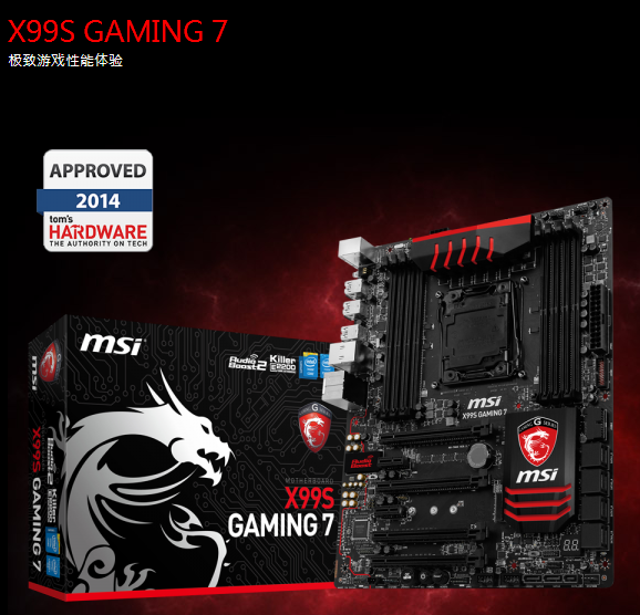
微星X99S GAMING 7主板支持Socket 2011-3架构的新一代Intel® Core™ Extreme® 处理器,Guard-Pro全能防护卫士:,强化的保护机制设计及能源功效设计,运用第四代图形化BIOS,轻松调整所有硬件状态。以下文档是微星X99S GAMING 7用户手册,为英文版本,有需要的朋友可立即下载此文档。
温馨提示:
本文档为PDF格式文档,因此需确保在阅读之前你已经安装了pdf阅读器,如果尚未安装阅读器,建议下载福昕pdf阅读器或其他PDF阅读器,进行安装后阅读。

微星X99S GAMING 7用户手册目录
Chapter 1 Getting Started............................................................................1-1
Packing Contents .................................................................................................1-2
Assembly Precautions ..........................................................................................1-3
Motherboard Specifications ..................................................................................1-4
Block Diagram ......................................................................................................1-7
Connectors Quick Guide ......................................................................................1-8
Back Panel Quick Guide ....................................................................................1-10
CPU (Central Processing Unit) ..........................................................................1-12
Introduction to the LGA2011-3 CPU ............................................................1-12
CPU & Heatsink Installation .........................................................................1-13
Memory ..............................................................................................................1-16
Up to Quad-Channel mode ..........................................................................1-16
Defined Channel list .....................................................................................1-16
Suggestions for Multi-Channel mode population rule ..................................1-17
Dual-Channel mode .....................................................................................1-17
Triple-Channel mode ...................................................................................1-17
Quad-Channel mode ...................................................................................1-17
Quad-Channel mode ...................................................................................1-18
Mounting Screw Holes .......................................................................................1-19
Power Supply .....................................................................................................1-20
JPWR1~2: ATX Power Connectors .............................................................1-20
Expansion Slots .................................................................................................1-21
PCI_E1~6: PCIe Expansion Slots ................................................................1-21
PCIe Bandwidth Table ................................................................................1-21
Video/ Graphics Cards ......................................................................................1-22
Single Video Card Installation ......................................................................1-22
Internal Connectors ............................................................................................1-23
SATA1~10: SATA Connectors ....................................................................1-23
SATA_EX1: SATA Express Connector .......................................................1-24
M2_1: M.2 Port ............................................................................................1-24
CPUFAN1~2,SYSFAN1~3: Fan Power Connectors ....................................1-25
JFP1, JFP2: System Panel Connectors ......................................................1-26
JUSB1~2: USB 3.0 Expansion Connectors .................................................1-27
JUSB3~4: USB 2.0 Expansion Connectors .................................................1-28
JCI1: Chassis Intrusion Connector ..............................................................1-28
JAUD1: Front Panel Audio Connector .........................................................1-29
AUDPWR1: Direct Audio Power Connector ................................................1-29
JTPM1: TPM Module Connector ................................................................1-30
Buttons ...............................................................................................................1-31
OC1: OC Genie Button ...............................................................................1-31
POWER1: Power Button ..............................................................................1-32
RESET1: Reset Button ................................................................................1-32
Jumper ...............................................................................................................1-33
JBAT1: Clear CMOS Jumper .......................................................................1-33
JSLOW1: Slow Mode Booting Jumper ........................................................1-33
Switch .................................................................................................................1-34
BIOS1: Multi-BIOS Switch ...........................................................................1-34
AUD_SW1: Audio Power Switch ..................................................................1-35
LED Status Indicators ........................................................................................1-36
LED Status Table .........................................................................................1-36
Debug Code LED Table ...............................................................................1-37
Drivers and Utilities ............................................................................................1-38
Driver/ Utilities Installation ...........................................................................1-38
Chapter 2 Quick Installation ........................................................................2-1
CPU Installation ...................................................................................................2-2
Memory Installation ..............................................................................................2-4
Motherboard Installation .......................................................................................2-5
Power Connectors Installation .............................................................................2-7
SATA HDD Installation .........................................................................................2-9
M.2 module Installation ......................................................................................2-10
Front Panel Connector Installation .....................................................................2-11
JFP1 Connector Installation .........................................................................2-11
Front Panel Audio Connector Installation ....................................................2-11
Peripheral Connector Installation .......................................................................2-12
USB2.0 Connector Installation .....................................................................2-12
USB3.0 Connector Installation .....................................................................2-12
Graphics Card Installation ..................................................................................2-13
Chapter 3 BIOS Setup .................................................................................3-1
Entering Setup .....................................................................................................3-2
Entering BIOS Setup .....................................................................................3-2
Overview ..............................................................................................................3-3
Operation .............................................................................................................3-6
Updating BIOS .....................................................................................................3-7
Updating the BIOS with M-FLASH .................................................................3-7
SETTINGS ...........................................................................................................3-8
System Status ................................................................................................3-8
Advanced .......................................................................................................3-9
Boot .............................................................................................................3-13
Security ........................................................................................................3-14
Save & Exit ..................................................................................................3-14
OC ......................................................................................................................3-16
M-FLASH ...........................................................................................................3-26
OC PROFILE .....................................................................................................3-27
HARDWARE MONITOR ....................................................................................3-28
Appendix A Realtek Audio .......................................................................... A-1
Software Configuration .........................................................................................A-2
Software panel overview ................................................................................A-2
Auto popup dialog ..........................................................................................A-3
Appendix B Intel RAID ................................................................................ B-1
Introduction ..........................................................................................................B-2
Using Intel Rapid Storage Technology Option ROM............................................B-3
Degraded RAID Array ........................................................................................B-10
System Acceleration (optional) ..........................................................................B-12
RST Synchronization (optional) .........................................................................B-14
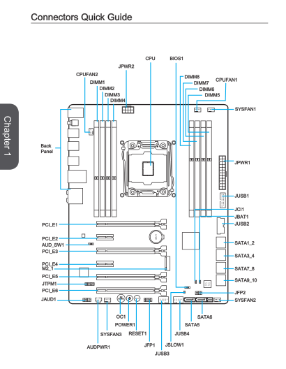
微星X99S GAMING 7用户手册——主板结构图
微星X99S GAMING 7规格参数
DDR4 内存 DDR4 2133/2200*/2400*/2600*/2666*/2750*/3000*/3110*/3333*(*OC) HMz
SATA Express 1
CPU 插槽 2011-3
CPU (最高支持) i7
M.2 port 1
系统总线 100 / 125 / 167MHz
芯片组 Intel® X99 Express Chipset
内存通道 Quad
内存插槽 8
最大内存 (GB) 128
PCI-Ex16 4
PCI-E Gen Gen3
USB 3.0 接口 (前端) 4
SATAIII 10 (*2x ports reserved for SATA Express)
USB 2.0 接口 (前端) 4
RAID 0/1/5/10
网络接口 10/100/1000*1
TPM 1
USB 3.0 接口 (背板) 8
USB 2.0 接口 (背板) 2
音源接口 (背板) 5+ Optical SPDIF
DirectX DX11
尺寸 ATX
SLI Y
3-way SLI Y
CrossFire Y
- PC官方版
- 安卓官方手机版
- IOS官方手机版


 保镖报警器使用说明书完整版
 天津公积金app用户手册doc格式免费版
 2021全国蚊子预报地图jpg 超大型高清版
 msteel工具箱使用教程pdf版
 ARM DS-5 调试器使用手册v5.16 pdf格式【原版】
 tokit产品说明书大全下载pdf 格式
 北汽ev200和ev160新能源汽车说明书pdf 完整版
 深入解析Windows操作系统第6版(上册)pdf彩色扫描版
 3dmax快捷键命令大全word格式
 仰邦科技无线投屏功能使用说明书1.0 免费版

 SONY索尼α7II(ILCA-7M2)使用说明书pdf格式
 中控iface702说明书doc 官方完速版
 Thermo-calc中文版(用户指导书)pdf格式电子
 卡西欧PRW-3000用户使用指南pdf格式【中文电
 3D3S操作说明书(共475页)pdf格式【高清电子
 配色设计原理高清pdf完整版